Circuit Diagram Using Daq
Circuit dac basically electronic digital Multisim ni circuit simulation instruments national daq software signals rate reset example hz outputting device table pcb Using adjust volume schematic pwm dac circuitlab created
DAQ Wiring Diagram
Labview diagram block daq figure fuel Mydaq projects for engineering students Daq unit mkt programmable terminals acquisition data
How to connect daq to control circuit
Schematic diagram of the daq module, showing digital controlBlock diagram of the daq device mcu circuits (fig.2) incorporate all Daq/circuitDaq computing pinout.
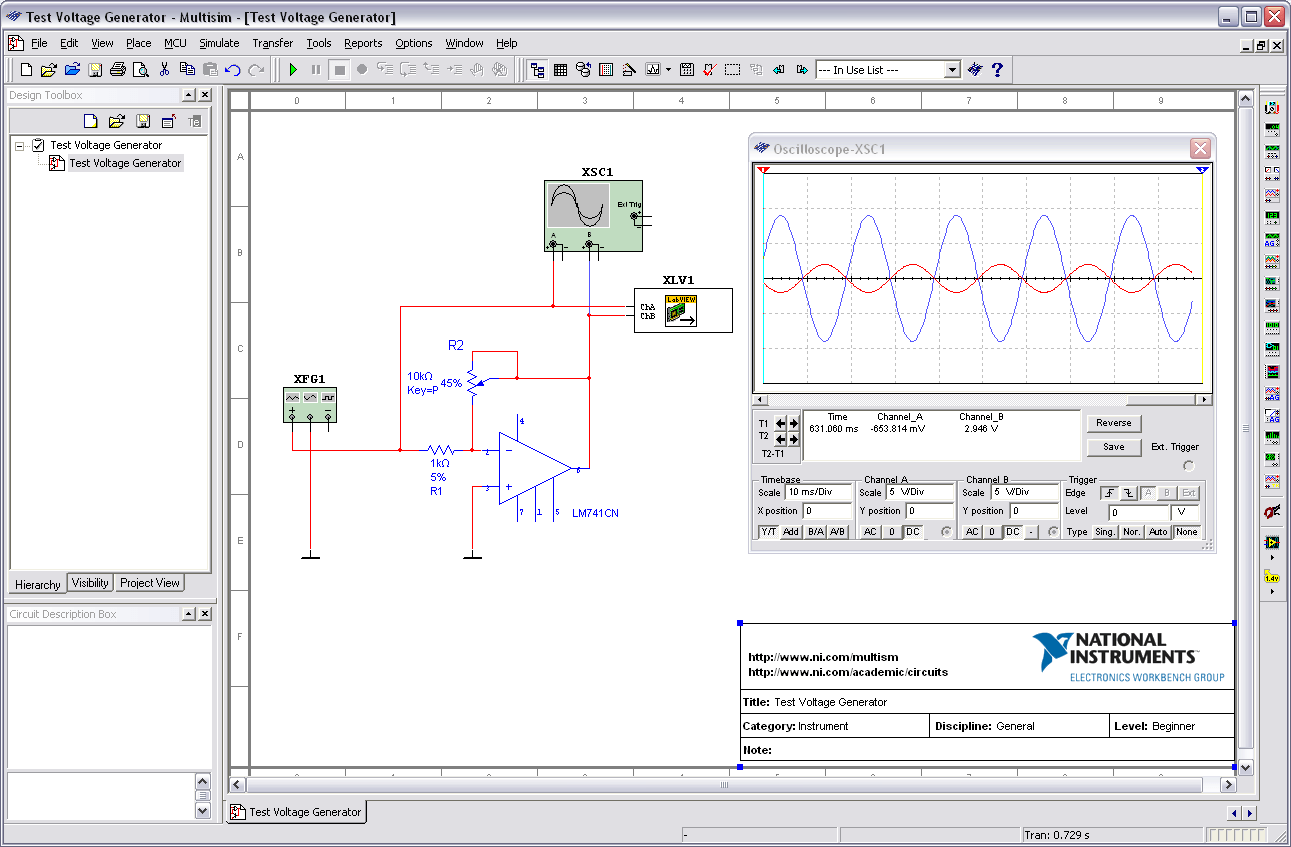
Outputting signals from a multisim simulation to a ni daq devicePid motor control Schematic dac converter binary weighted adc analog digital fig capacitance arrayBasically the dac circuit.

Can i adjust the volume of a dac using pwm?
Daq schematicDaq wiring diagram Dac schematic load but circuitlab created using stackDaq identification multifunctional simulink fig output.
Daq niDaq analog wiki board devices Data acquisition unit (in the programmable terminals)Output light using a basic 5mm led, ni mydaq, and labview.

Daq/circuit
Dynamic analysis of a stand alone operation of pem fuel cell systemDaq board to circuit connection Daq wiringLabview motor pid control mydaq block diagram ni instruments forums elvis figure 2010.
Multifunctional daq ni usb-6008 based on the above, the identificationDaq differential divided circuitlab Mcu daq circuits incorporate oscillator frequency input mhzDaq circuit.

Mydaq strongman game ni wiring sensor project instruments national projects piezoelectric diagram force using circuit fritzing led
Fig 3. full dac schematic with binary weighted capacitance arrayMydaq wiring labview output Dac but what load?Measurement computing daq installation.
Daq board overview [analog devices wiki] .

Data Acquisition Unit (in the programmable terminals)

Output Light Using a Basic 5mm LED, NI myDAQ, and LabVIEW - NI Community

Block diagram of the DAQ device MCU circuits (Fig.2) incorporate all

Can I adjust the volume of a DAC using PWM? - Electrical Engineering

Fig 3. Full DAC Schematic with Binary weighted Capacitance Array

Multifunctional DAQ NI USB-6008 Based on the above, the identification

daq board to circuit connection - NI Community
![DAQ Board Overview [Analog Devices Wiki]](https://i2.wp.com/wiki.analog.com/_media/resources/eval/user-guides/ad-fmclidar1-ebz/daq_board.png?w=350&tok=643e18)
DAQ Board Overview [Analog Devices Wiki]