Circuit Diagram Of Decimal Adder
Decimal to bcd decoder Full adder circuit: theory, truth table & construction What is meant by arithmetic circuits?
Adder - Classifications, Construction, How it Works and Applications
Adder bcd decimal binary coded digital electronics carry output parallel stage digits next Binary adder and subtraction circuits along with its various types Adder logical gate obtained sum
Adder circuit construction binary circuits ibm sourav gupta
The two half adder circuits cascaded together forms a full adderBinary coded decimal adder (4 bit) 13+ full adder block diagramDigital electronics: binary coded decimal (bcd) adder.
Adder bit decimal bcd binary coded arithmetic addersAdder logic half implementation Adder cascadedAdder circuits arithmetic circuit logic diagram meant given below.

Proposed 1-digit bcd adder circuit.
Circuit diagram adder common seekicBcd circuit decimal decoder diagram keypad seekic convert circuits converter ic will schematic fair science projects input why basic key Adder bcd digit circuit proposedAdder 14t.
Adder half circuits subtraction encoding watelectronicsAdder circuit logic subtractor electronics boolean gates outputs 14t full adder circuit diagram.Adder in digital electronics, half adder and full adder in digital.
Common adder circuit diagram
.
.


14T full adder circuit diagram. | Download Scientific Diagram

Adder in Digital Electronics, Half Adder and Full Adder in Digital

Binary coded decimal adder (4 bit)
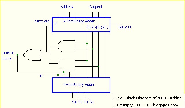
Digital Electronics: Binary Coded Decimal (BCD) Adder

Decimal to BCD Decoder - Basic_Circuit - Circuit Diagram - SeekIC.com

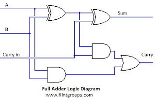
Full Adder Circuit: Theory, Truth Table & Construction

The two half adder circuits cascaded together forms a full adder

Common adder circuit diagram - Other_Circuit - Basic_Circuit - Circuit

Adder - Classifications, Construction, How it Works and Applications